4. Qmix I/O-B Module
4.1. Configuring a bus terminal
4.1.1. Overview
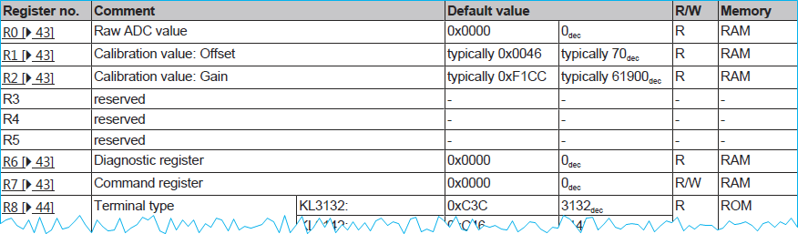
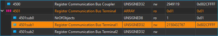
The QmixIO-B module is equipped with a series of bus terminals with different functions, depending on the configuration. Each individual bus terminal contains a set of registers for configuration or for reading status information. These registers are numbered starting at 0 and can therefore be easily addressed via the index. The following picture shows the register overview of the KL3162 analog input terminal.
Tip
To obtain an overview and description of all registers for a specific terminal, simply download the documentation for the terminal from Beckhoff.
4.1.2. Device parameter access
To access and configure a certain bus terminal you can use the QmixElements CANopenTools Plugin.
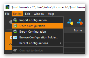
To open the CANopenTools Plugin, start the QmixElements software and select from the main menu the menu item .
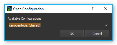
Then select the canopentools configuration:
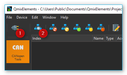
Connect your QmixIO-B module or your Beckhoff bus coupler with your PC and turn it on. Then click the Connect ❶ button in the QmixElements software and scan for connected devices ❷.
The software should detect the connected module ❶. Click with the right mouse button on the entry with the detected device and select
Assign EDS File❷ (see figure below).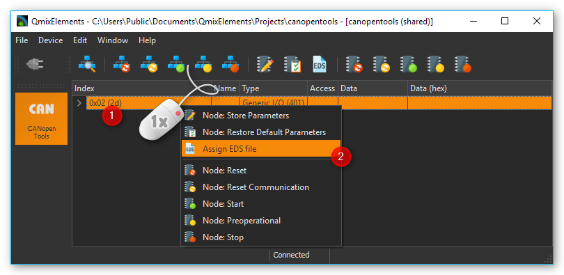
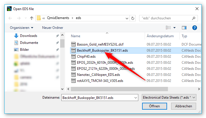
Select the valid EDS file for the Beckhoff BK5151 bus coupler from the existing EDS-files.
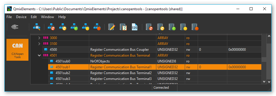
Now navigate to the object dictionary entry 0x4501– Register Communication Bus Terminal. Select the sub entry (0x4501subx) that matches the channel of your bus terminal that you want to configure.
The bus terminals are numbered in the order they are attached to the bus coupler. I.e. if you have two terminals and the first terminal is an analog input terminal and the second terminal is a thermocouple terminal, then the object dictionary entry would be 0x4501sub2 – Register Communication Bus Terminal 2 for the configuration of the thermocouple bus terminal.
4.1.3. Register access
Register values are read and written via the corresponding object dictionary entry for the terminal 0x4501subX where “X” is the index of the terminal. The register is accessed by reading and writing a 32-bit value. The following table shows the bits of this 32–bit value:
31 |
30 - 24 |
23 - 16 |
15 - 9 |
7 - 0 |
|---|---|---|---|---|
Access bit |
Channel number |
Register number |
High byte register value |
Low byte register value |
MSB |
LSB |
Access bit: 0 = read access, 1 = write access
Channel number: If a bus terminal has multiple channels, like the Kl3162 bus terminal with 2 analog input channels, this channel number addresses the corresponding channel of the terminal. Channel number 0 corresponds here to the first channel, 1 to the second channel, and so forth.
Register number: The register that should be accessed. Read the bus terminal documentation for a register overview.
Register value: The 16-bit register value consists of high and low byte.
4.1.4. Reading register values
To read a register value, you first need to write to object 0x4501subX to identify the channel and the register and then you can read the register value from the same object. So each read consists of a write access followed by a read access from the same object.
The following example shows how to read a parameter. For this example, we assume that we want to read the calibration interval (register 40) from the second channel of the KL3162 analog input terminal.
This terminal is the 1st terminal on our QmixIO-B module so we need to access the object dictionary entry 0x4501sub1.
To read the calibration offset value, we first need to write the following value:
Access bit 0 = read access
Channel number 1 (0 = first channel, 1 = second channel …)
Register index 40 (Calibration interval) hexadecimal 28
Register value 0
So we have the following value that we need to write: 0x01280000
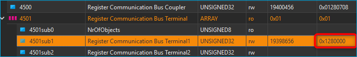
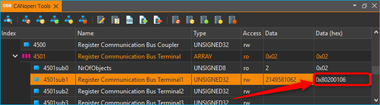
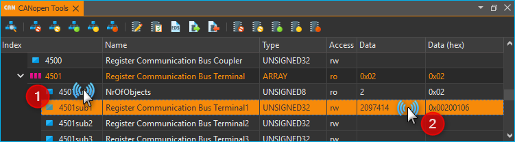
To see the value that has been read from device, you need to click on another object ❶, e.g. 4501sub0 and then click on the index 0x4501sub1 again ❷. This will trigger a read of the object 4501sub1.
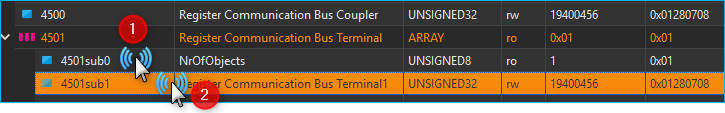
Now you can see the value read from the device. It is 01280708.
So the value read from the device contains the same configuration for Access bit, channel number and register index, but the register value field has been updated with the value read from device. The hexadecimal value of 708 corresponds to 1800 decimal. The calibration value is given in multiple of 100 ms so the 1800 indicates a calibration interval of 180 seconds.
4.1.5. Writing register values
Before you can change any register value of a terminal channel, you need to disable the write protection for the channel. In normal mode all user registers are read-only with the exception of Register 31. In order to deactivate this write protection you must write the code word (0x1235) into Register 31. If a value other than 0x1235 is written into Register 31, write protection is reactivated.
Please note that changes to a register only become effective after restarting the terminal (power off/power-on). So to deactivate write protection, the value 0x1y1F1235 (y = Channel number) needs to be written first.
For the following example we want to change the calibration interval of the first channel of a KL3162 dual channel analog output terminal to 300 seconds. The first step we need to do is to disable write protection for the first channel. This terminal is the 1st terminal on our QmixIO-B module so we need to access the object dictionary entry 0x4501sub1.
Step 1 - Removing Write Protection
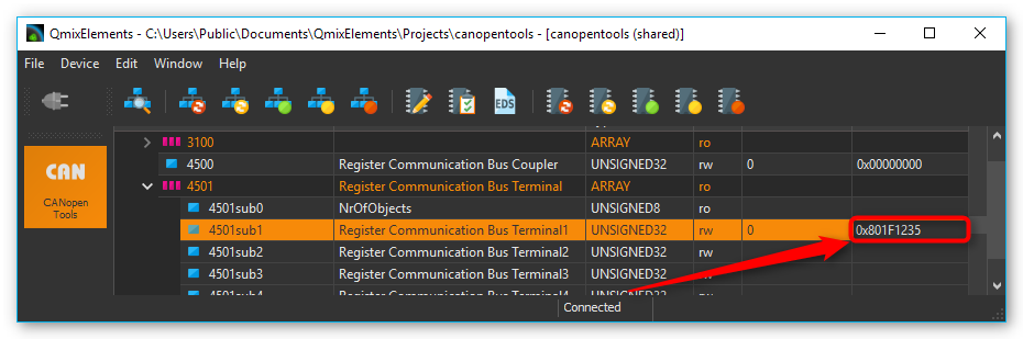
First we disable write protection by writing the codeword 1235 to the register 31:
Access bit 1 = write access
Channel number 0 (0 = first channel, 1 = second channel …)
Register index 31 (Code word register) –> hexadecimal 1F
Register value 1235
So we write the following value to disable write protection: 0x801F1235
Step 2 - Writing new Value
Now we can change the calibration time:
Access bit 1 = write access
Channel number 0 (0 = first channel, 1 = second channel …)
Register index 40 (Calibration interval) –> hexadecimal 28
Register value 300 seconds, the value is given in multiple of 100 ms, that means value is 3000 decimal –> hexadecimal 0BB8
So we write the following value to change the calibration interval to 300 seconds: 0x80280BB8
Step 3 - Reading back written value
Now we can verify the written value by reading the register value back.
Access bit 0 = read access
Channel number 0 (0 = first channel, 1 = second channel …)
Register index 40 (Calibration gain) –> hexadecimal 28
Register value 300 seconds, the value is given in multiple of 100 ms, that means value is 3000 decimal –> hexadecimal 0000
So we write the following value to read the calibration interval: 0x00280000
Click on another object dictionary entry and then on this entry again, to force an update of the value read from device, like it is written in the section Reading register values.
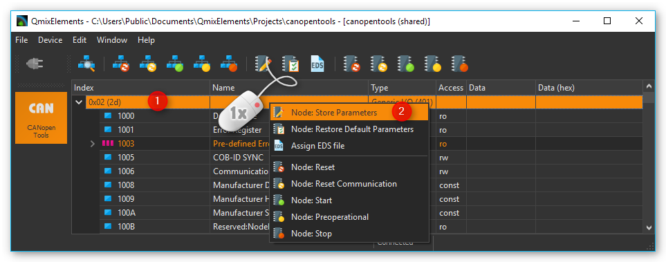
Step 4 - Storing data persistently
If you have configured all channels properly, you can write the configuration persistently into the non-volatile memory of the Beckhoff device. Click with the right mouse button into the device entry ❶ and select Node Store Parameters from the context menu ❷.
4.2. KL316x - Analog input terminal 0…10 V
4.2.1. Configuring Auto Calibration
To configure the KL316x terminal you can use the QmixElements CANopenTools Plugin. Please read the section Configuring a bus terminal to learn how to read and write registers of a bus terminal.
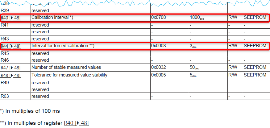
Sometimes the Auto Calibration of the KL316x analog input terminal may fail or cause problems. You can prevent this by disabling auto calibration and setting the interval for forced calibration to a very long time. The following picture shows relevant registers of the bus terminal (copied from manual).
Important
Before you can change any value, you need to disable write protection for the channel of the terminal. Read the section Removing Write Protection to learn how to disable the write protection for the registers of a single channel.
If write protection is removed, we can start writing other registers.
First you can set the calibration interval (R40) to the maximum value 0xFFFF decimal 65536. The value is given in multiple of 100 ms so this means calibration interval of 6553 seconds:
Access bit 1 = write access
Channel number y (0 = first channel, 1 = second channel …)
Register index 40 (Calibration interval) –> hexadecimal 28
Register value maximum –> hexadecimal FFFF
Write value 0x8y28FFFF to object 0x4501subX and replace y with the channel number. You can now read the value back, to verify if it has been written properly by writing 0x0y280000.
Now we also set the interval for forced calibration (R44) to a maximum value 0xFFFF:
Access bit 1 = write access
Channel number y (0 = first channel, 1 = second channel …)
Register index 44 (Interval for forced calibration) –> hexadecimal 2C
Register value maximum –> hexadecimal FFFF
Write value 0x8y2CFFFF to object 0x4501subX and replace y with the channel number.
You can now read the value back, to verify if it has been written properly by writing 0x0y280000.
Then you can disable auto calibration via the feature register R32.
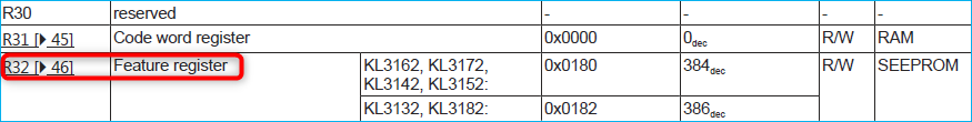
Tip
This register contains several configuration bits. Read the KL316x manual for a detailed description of the bits in the feature register.
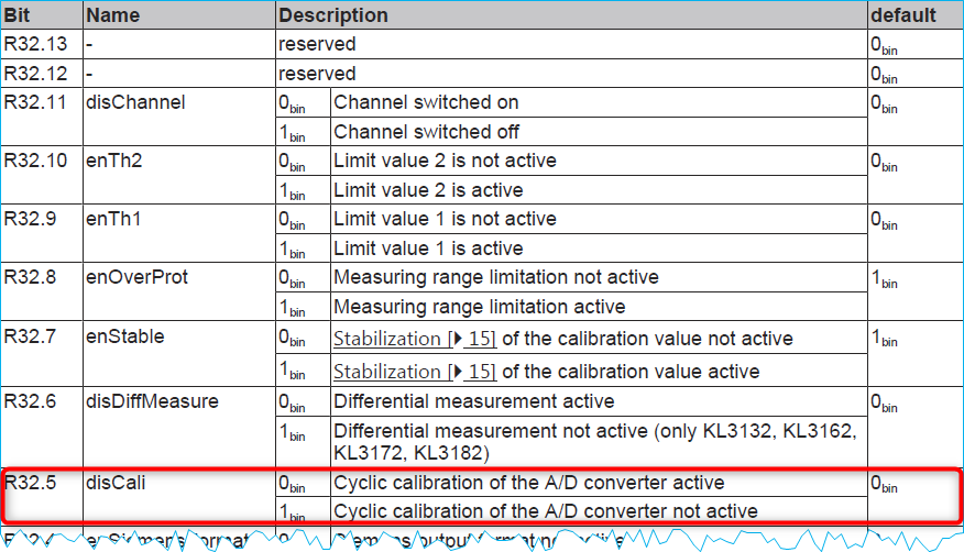
So we need to set Bit 5 of this register to 1 to disable. To ensure that no other bits are modified, you first need to read the register value from the device:
Access bit 0 = read access
Channel number y (0 = first channel, 1 = second channel …)
Register index 32 (Calibration gain) hexadecimal 20
Register value 0000
We write the following value to read the feature register: 0x00200000.
Normally the device should return the default configuration value: 0. Now you can set bit 5 – that means the value to write will be the value read from device ored with 0x0020 (Bit 5 set).
Access bit 1 = read access
Channel number y (0 = first channel, 1 = second channel …)
Register index 32 (Calibration gain) hexadecimal 20
Register value 0020
Write value 0x8y200020 to object 0x4501subX and replace y with the channel number. You can now read the value back, to verify if it has been written properly by writing 0x0y200000.
If you have configured all channels properly, you can write the configuration persistently into the non-volatile memory of the Beckhoff device like written in section Storing data persistently.
4.3. KL320x – PT100 (RTD) Terminal
4.3.1. Configuring Sensor Type
To configure the thermocouple type of a KL320x terminal you can use the QmixElements CANopenTools Plugin. Please read the section Configuring a bus terminal to learn how to read and write registers of a bus terminal.
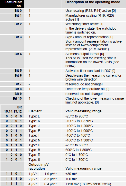
You can select the sensor type via the feature register (32) of the KL320x bus terminal. Here is a snippet from the KL320x manual that shows the register R32. You can select the type via bits 12-15.
Feature bit no.
Description of the operating mode
Bit 0
1
User scaling (R33, R44) active [0]
Bit 1
1
Manufacturer scaling (R19, R20) active [1]
Bit 2
1
Watchdog timer active [1]
(In the delivery state, the watchdog timer is switched on.)
Bit 3
1
Sign / amount representation [0]
(Sign / amount representation is active instead of two’s- complement representation (-1 = 0x8001). )
Bit 4
1
Siemens output format [0]
(This bit is used for inserting status information on the lowest 3 bits (see below). )
Bit 5, 6
/
reserved, do not change.
Bit 7
1
Activates filter constant in R37 [0]
Bit 8
1
Over range Protection [1]
(If the temperature exceeds 850°C the status bits are correspondingly set and the output value is 850°C. )
Bit 9
/
reserved, do not change
Bit 10
1
Two-wire connection [0]
Bit 11
/
reserved, do not change
Bit 15, 14, 13, 12
Element
Valid measuring range
0000
PT100
-200°C to 850°C
0001
NI100
-60°C to 250°C
0010
PT1000
-200°C to 850°C
0011
PT500
-200°C to 850°C
0100
PT200
-200° C to 850°C
0101
NI1000
-200°C to 850°C
0110
NI120
-80°C to 320°C
1110
Output in Ω
10.0 Ω to 5000.0 Ω
1111
Output in Ω
10.0 Ω to 1200.0 Ω
When writing data to the terminal or reading data to the terminal, the register value of the feature register is mapped into the lower 16 bits of the 32 bit message value:
31
30 - 24
23 - 16
15 - 12
11 - 0
Access bit
Channel number
0x20 (decimal 32)
Feature register value - Sensor Type
Feature register value - Other Feature Bits
MSB
LSB
Now navigate to the object dictionary entry 0x4501– Register Communication Bus Terminal. Select the sub entry (0x4501subX) that matches the channel of your thermocouple terminal. I.e. if you have two terminals and the first terminal is an analog input terminal and the second terminal is your thermocouple terminal, then the object dictionary entry would be 0x4501sub2 – Register Communication Bus Terminal 2.
Before you can change any register value of a terminal channel, you need to disable the write protection for the channel. Read section Removing Write Protection to learn how to disable the write protection.
To disable write protection for a channel, write 0x8y1F1235 to the channel. Replace the y with the channel number. If you would like to change the first channel (channel 0) then write 0x801F1235 to the terminal register.
Now you can write the RTD sensor type to the terminal. Use the values from the feature register table above. Replace y with the channel number. Please note, that writing the feature register may change other bits in the feature register:
PT100 – 0x8y200106
PT1000 – 0x8y201106
To configure the PT100 sensor for channel 0 write 0x80200106 to the terminal.
Now you can verify that the thermocouple has been configured properly, by reading back the configured register value. To do this, first write 0x0y200000 to the terminal. (e.g. 0x00200000 for channel 0).

Then click on sub index 0 and then on the sub index of the terminal, to update the value.
If you have configured all channels properly, you can write the configuration persistently into the non-volatile memory of the Beckhoff device like written in section Storing data persistently.
4.4. KL331x - Thermocouple Terminal
4.4.1. Configuring Thermocouple Type
To configure the thermocouple type of a KL331x terminal you can use the QmixElements CANopenTools Plugin. Please read the section Configuring a bus terminal to learn how to read and write registers of a bus terminal.
You can select the thermoelement type via the feature register (32) of the KL331x bus terminal. Here is a snippet from the KL331x manual that shows the register R32. You can select the type via bits 12-15.
When writing data to the terminal or reading data to the terminal, the register value of the feature register is mapped into the lower 16 bits of the 32 bit message value:
31
30 - 24
23 - 16
15 - 12
11 - 0
Access bit
Channel number
0x20 (decimal 32)
Feature register value - Sensor Type
Feature register value - Other Feature Bits`
MSB
LSB
Now navigate to the object dictionary entry 0x4501– Register Communication Bus Terminal. Select the sub entry (0x4501subX) that matches the channel of your thermocouple terminal. I.e. if you have two terminals and the first terminal is an analog input terminal and the second terminal is your thermocouple terminal, then the object dictionary entry would be 0x4501sub2 – Register Communication Bus Terminal 2.
Before you can change any register value of a terminal channel, you need to disable the write protection for the channel. Read section Removing Write Protection to learn how to disable the write protection.
To disable write protection for a channel, write 0x8yF11235 to the channel. Replace the y with the channel number. If you would like to change the first channel (channel 0) then write 0x80F11235 to the terminal register.
Now you can write the thermocouple type to the terminal. Use the following values for the different types:
Typ K – 0x8y201026
Typ J – 0x8y202026
To configure the Typ K thermocouple for channel 0 then write 0x80201026 to the terminal.

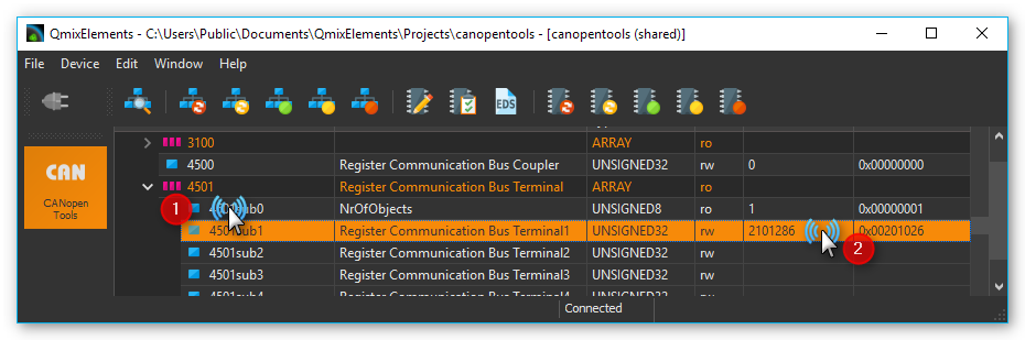
Now you can verify that the thermocouple has been configured properly, by reading back the configured register value. To do this, first write 0x0y200000 to the terminal. (e.g. 0x00200000 for channel 0).
Then click on sub index 0 and then on the sub index of the terminal, to update the value.
If you have configured all channels properly, you can write the configuration persistently into the non-volatile memory of the Beckhoff device like written in section Storing data persistently.
4.5. Adding Terminals
Before you start, please contact the application and sales team of CETONI and tell them which device you are going to update (CET-number) and which terminals you are going to add to your Qmix-I/O-B. CETONI will send you an updated device database which you have to import into your QmixElements software or, if necessary, an updated software version if the terminals are not supported by QmixElements at the moment. After you have imported the updated device database or reinstalled the software, please perform the following instructions.
Step 1 - Preparations
Please add your Qmix-I/O-B module only to your Qmix system and check that your device is switched off. Physically add your new terminals to your Qmix-I/O-B. Terminate the Qmix-I/O-B with the Beckhoff KL 9010 end terminal. Finally switch on your device.
Attention
Do not forget to terminate your Qmix-I/O-B using the KL 9010 bus end terminal. Otherwise the device will not work..
Step 2 - Restore Factory Default Settings
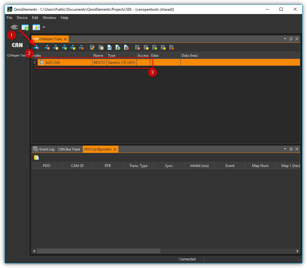
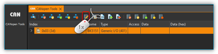
Factory default settings need to be restored in order to let the device properly set up it’s communication parameters. Therefore in QmixElements load the device configuration canopentools. Connect the software to your Qmix system and scan for devices connected to your base module. A generic I/O device should be displayed (see figure below).
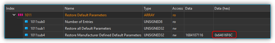
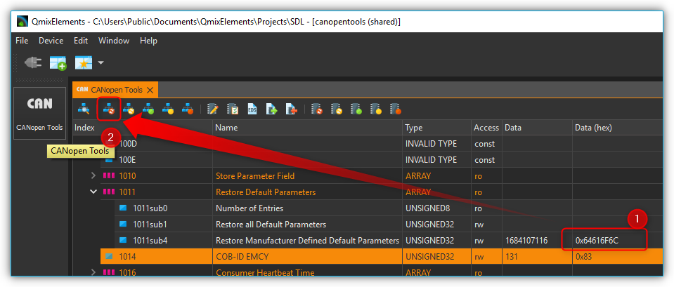
Next please look for the object dictionary entry 1011 Restore default parameters. In sub-index 4 Restore Manufacturer Defined Default Parameters please enter the value 0x64616F6C in Data (hex). Subsequently please reset the device pressing the All nodes: Reset button (please see figures below).
Step 3 - Adapt Inhibit Time and Save Parameters
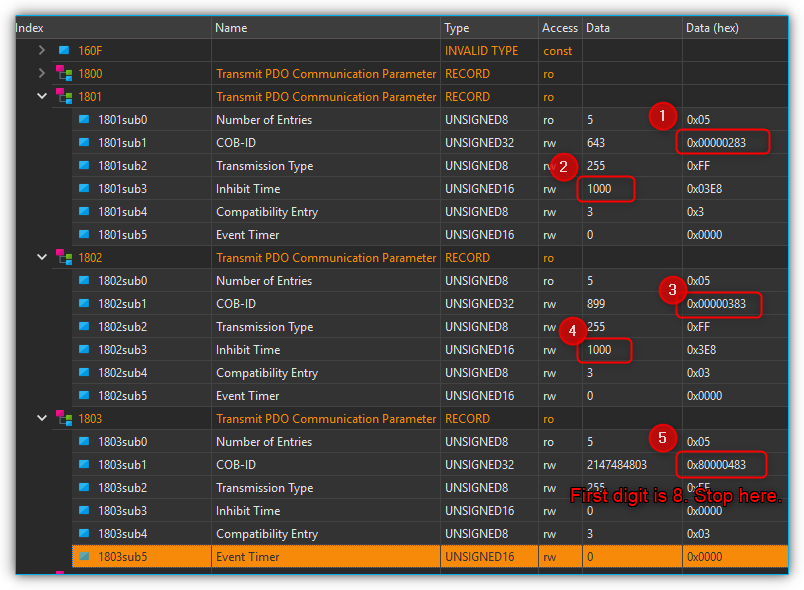
Now you need to set the inhibit time of all Transmit PDO Communication Parameter entries for analog input devices. Starting from object dictionary entry 1801 till 1803, please click the sub-index 1 COB-ID and check whether the first digit in Data (hex) is 8. If it is not, in sub-index 3 Inhibit Time please enter the value 1000 in the Data field. If you have found a COB-ID carrying 8 as the first digit in Data (hex), the communication parameter is deactivated. That means you have successfully finished this step (please see figure below).
Important
Object dictionary entry 1800 is reserved for digital input channels. Please leave it’s configuration untouched.
Finally you’ll just have to save the configured parameters by pressing the Node: Store Parameters button and accept the following question for storing the parameters permanently to the device.(please see the figure below).
You have finished adding the new terminals and should now be able to create a new device configuration with your updated Qmix-I/O-B device and use it within your application.