8. CSV Data Logger
8.1. Introduction
The data logger plug-in provides the user with a powerful tool to record any of the data provided by connected devices in a user-defined time interval. Data are written into a CSV file (CSV: comma/character-separated values). This text file format is commonly used to save and exchange simply-structured data.
Tip
CSV files can be opened and worked with in spreadsheet applications, such as Microsoft Excel if the correct value-separating and decimal sign has been used.
8.2. Configuration Dialogue
8.2.1. Open the Configuration Dialogue

When the data logging plug-in has been loaded, the toolbar will display two additional buttons for the configuration of the logging of data ❶ and to start/stop the logging process ❷.
8.2.2. Overview CSV-Logger Configuration Dialogue
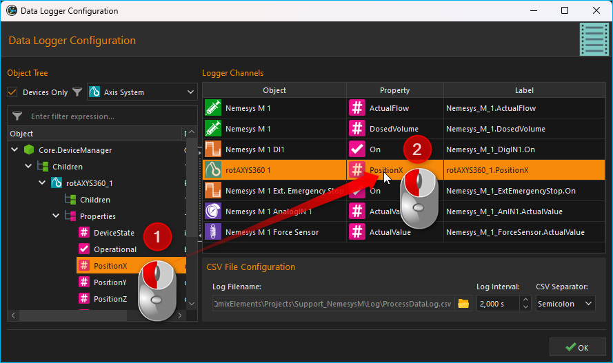
Once the data logging configuration has been activated, the following configuration dialogue will be displayed:
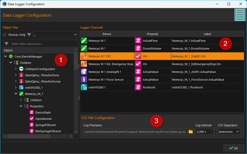
The configuration dialogue contains the following elements:
Object Tree - The Object Tree contains a tree of all objects and their properties that are present in the application. You can use various filters to filter the object tree for specific objects. By default, only devices and device properties are displayed.
Logger Channels - lists all channels that may be recorded by the logger.
CSV File Configuration - allows the user to set various settings for the data logging file.
8.2.3. Object Tree
In the Object Tree you will find a hierarchical list of all objects (e.g. devices) and their child objects (such as child devices):
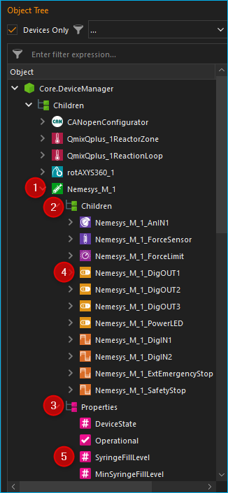
Object - An object can be, for example, a device (here Nemesys_M_1) or another application object. You will find the two elements Children and Properties in each object after expanding it in the next level.
Children - The Children element groups all child objects of the parent object. In our example, these are all objects or devices that are subordinate to the device Nemesys_M_1 or belong to this device.
Properties - The Properties element groups all properties of the parent object. In our example, these are all the properties of the Nemesys_M_1 device that can be recorded in the logger.
Child Object - All child objects can be found in the Children group. In the example Nemesys_M_1, these are, for example, the digital and analogue inputs and outputs of the device, such as Nemesys_M_1_DigOUT1. These objects can in turn be expanded to display their child objects and properties.
Property - In the Properties group you will find all properties of the parent object. In the example of Nemesys_M_1, these are, for example, the properties SyringeFillLevel or ActualFlow. You can simply drag and drop these properties into the channel list to record their values.
8.2.4. Filtering the Object Tree
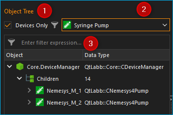
Above the object tree you will find various filters with which you can filter the object tree according to certain criteria. The Devices Only ❶ checkbox is activated by default. This means that only devices that are managed by the internal device manager (Core.DeviceManager) are displayed in the object tree. If you deactivate this checkbox, other application objects are displayed in the object tree.
If the Devices Only❶ checkbox is activated, a selection box ❷ is displayed with which you can filter the device tree according to a specific device type. In the illustration below, for example, the tree was filtered for syringe pumps:
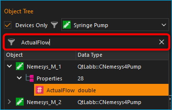
In addition, you will find an input field ❸ directly above the object tree, with which you can filter the object tree according to a specific term, e.g. a device name or a device property. In the image below, for example, a filter has been set for the device property ActualFlow. This means that only objects or devices with this property are displayed in the object tree:
8.2.5. List of Logger Channels
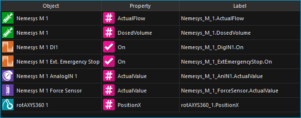
The table Logger Channels shows the configuration of the logger. Each row in that table corresponds to one column in the recorded CSV file. The following columns are available:
Object - contains the name of the object from which the value of a certain property is to be recorded and the icon of the object.
Property - this is the name of the object property/process data value that will be recorded. Its type (numeric or boolean) can be identified by the displayed icon.

Numeric value

Boolean value

Text value
Label - allows you to define a customized description for the selected channel. This description will be used as the column header in the CSV file.
In order to add a channel to the data logging process, simply follow the steps below.
8.3. Logger Configuration
8.3.1. Add Logger Channels
Step 1- Adding of Channels
Drag-and-Drop the object property you want to record from the Object Tree into the Logger Channels list. The new channel is inserted in the line where you release the mouse button (see figure below).
Tip
To simplify the selection of an object property, you can filter the object tree according to various criteria.
Step 2 - Setting the Channel Label
In the column Label you can customize the label for each channel. This label will be used as the column header of the CSV file for the selected channel.
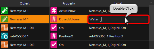
To do this, double-click into the respective table cell that is to be changed and insert the new description (see figure above).
Important
Upon choosing a new device property, a new channel description will be assigned automatically. That is, you should change the channel label only once the correct device property has been selected.
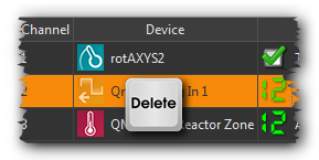
8.3.2. Deleting Channels
Highlight the desired channels using the mouse to delete one or more channels from the list, and then use either the Delete key or the item of the right-click context menu:
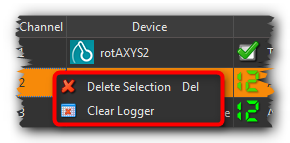
To delete the entire channel list, use the context menu item .
8.3.3. Configuration of CSV Properties
In the CSV File Configuration section you can set the global properties of the CSV logger as well as the format of the recorded data (see figure below).
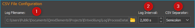
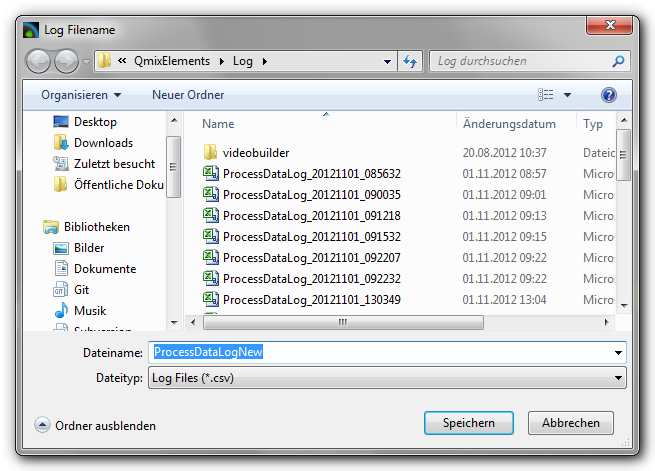
Select File Name and Folder
Set the file name and location of the log file via Log Filename ❶. For this, click on the folder symbol on the right, select the target folder and give a file name.
Setting the Recording Interval
Set the time interval at which the data of all channels is to be recorded via the field Log Interval ❷. The time unit for the interval is seconds and you may set it in 0.1 second increments.
Important
Choose the recording interval as large as possible and as small as necessary. This will minimize amount of data that will be recorded.
Set the Separating Character
The character that will be used to separate individual data (columns) needs to be set via the selection field CSV Separator ❸. Depending on the software that is to be used for data evaluation, the character that needs to be used may change.
Tip
To obtain a CSV file that can be imported into Microsoft Excel, the semicolon (;) should be used.
Important
All configuration settings of the process data logger will be saved upon closing the configuration dialogue and are available when the application will be restarted.
8.4. Start/Stop of the Logging Process

Use the relevant toolbar button to start and stop the data logging process.
A new data file will be created each time the logging process is
started. A time stamp with date and time will be added as a suffix to
file name _YYYYMMDD_hhmmss. That means, if the file name
ProcessDataLog.csv has been assigned by the user, starting the logging
process on November 05, 2012 at 10:32 am and 9 secondswill create a
logging file with the name ProcessDataLog_20121105_103209.csv.
This ensures, that a new logging file with a unique time stamp will be
created each time the logging process is started.
8.5. Log File Data Format
The recorded CSV files have the following structure:
Each CSV file consists of multiple data sets organized in rows and separated by line breaks.
Each data set consists of a number of data fields (columns) that are separated by a specific character (e.g., semicolon).
The first column always contains the relative time point (in seconds) of the corresponding data set.
The first row shows the channel labels as configured by the user.
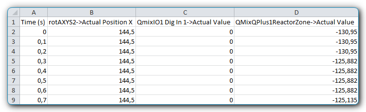
To obtain the absolute time stamp for a data set, you may simply add an extra column to the spreadsheet and calculate the time by adding the data set’s relative time to the absolute time given in the file names time stamp.
Tip
The absolute time stamp at which logging started is given in the file name of the log file.